CONTENTS
1. Parallel Shaft Gears
– Spur Gear
– Helical Gear
– Herringbone or Double Helical Gear
2. Intersecting Shaft Gears
– Straight Bevel Gears
– Miter Gear
– Spiral Bevel Gears
– Zerol Bevel Gears
3. Non parallel non intersecting shafts
– Crossed Helical Gears
– Worm Gears
– Hypoid Gears
4. Rack and Pinion
PARALLEL SHAFT GEARS
As the name suggests, parallel shaft gears refer to the gears which are used for power transmission between two shafts which are parallel to each other. Types of such Parallel Shaft Gears are enlisted and described below:
A. SPUR GEAR
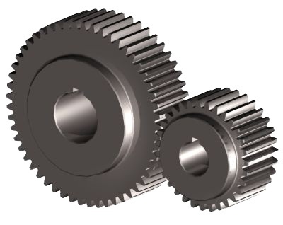
- Spur gears are the simplest gears that can be mounted on parallel shafts.
- Manufacturing is simple and easy.
- The teeth of the gears are parallel to the shaft.
- It is suitable for carrying pure torsion, but it cannot be used where axial loads are present.
- Operation is noisy and the teeth are subjected to high impact stresses due to sudden mating while rotation.
B. HELICAL GEARS
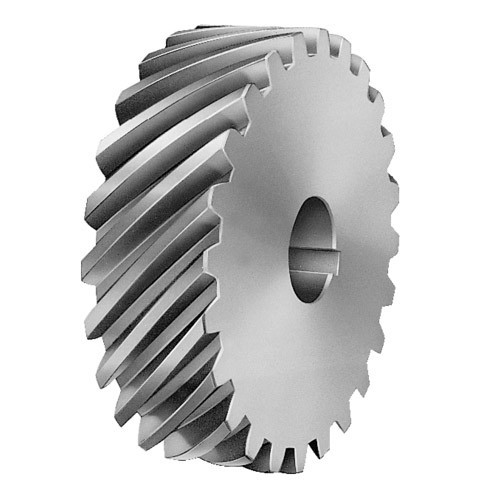
- In helical gears, the teeth are inclined at an angle and its shape is such that it is a part of a helix.
- Due to inclination of teeth, the contact between two teeth is gradual and smooth. Hence operation is smoother and less noisier.
- Due to the same reason, the teeth are subjected to less stress and can have longer lives.
- Even while carrying pure torsional loads, due to inclined teeth, an axial component of load is generated. It has to be borne by the bearings and hence, it can have detrimental effect on the life of the bearings.
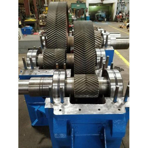
C. HERRINGBONE OR DOUBLE HELICAL GEARS
- Herringbone gears are nothing but two sets of helical gears with teeth inclined in opposite direction.
- Sometimes two opposite handed helical gears are used together and in some cases, one single gear which has the pattern of opposite handed helix on two sides, is used.
- It has all the advantages of helical gears.
- Additionally, the problem of axial loads do not arise in herringbone gears because the axial components are directed opposite to each other and hence they get balanced.
- Its manufacturing is slightly complex and it is expensive. So, it is used only for more sophisticated applications.
INTERSECTING SHAFT GEARS
Here we shall see a few cases where the two shafts between which power transmission takes place are not parallel. In other words, they would intersect each other when their axes are extended.
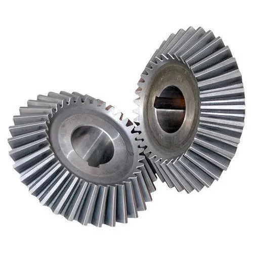
A. STRAIGHT BEVEL GEAR
- The two shafts are inclined to each other at some angle.
- The external appearance of the gear is not cylindrical, rather it is like the frustum of a cone.
- The teeth are straight (not helical) but they are at an angle to the transverse plain.
B. MITER GEARS
- Miter gears are nothing but a special case of Bevel gears where the two axis are exact perpendicular, that is, when their axes are extended, they would intersect at an angle of 90 degrees.
C. SPIRAL BEVEL GEAR
- Spiral bevel gears are nothing but a modified type of bevel gears.
- Straight bevel gears were like spur gears but for intersecting axes and they had similar problems that spur gears had like sudden engagement of mating teeth, resulting in higher values of stresses and and noise.
- In spiral gears, the teeth are curved and hence they don’t engage all of a sudden. Thus, both noise and stresses are reduced.
- It is slightly complex in design and expensive to manufacture.

D. ZEROL BEVEL GEARS
- Zerol bevel gears are a special case of spiral bevel gears.
- In zerol bevel gears, the teeth are curved in such a way that the slope of a teeth at the mid point is zero. In other words a tangent at the mid point of the teeth would be perpendicular to the plane of the axis.
NON PARALLEL NON INTERSECTING SHAFT GEARS
In this case, the two shafts are neither parallel and nor do their axes meet at any point. Under such a scenario, we can use the following type of gear drives.
A. CROSSED HELICAL GEAR
- Two helical gears are used of similar tooth spacing and angle of helix.
- They are placed over one another perpendicularly.
- It is done in such a way that the teeth of one gear is able to mesh with the other gear as shown in the diagram.

B. WORM GEAR
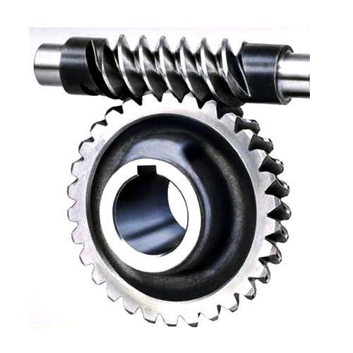
- In worm gears, there is one spur gear and a threaded shaft. The threads of the shaft meshes with the teeth of the gear.
- When the shaft is given a single rotation, the teeth gets displaced by a distance equal to the pitch of the screw thread.
- It is especially useful where speed is needed to be greatly reduced.
C. HYPOID GEAR
- It is very similar in appearance to spiral or helical bevel gears.
- The difference is that one of the shaft is a pinion, meant to rotate at high speed while the other is a gear, meant to rotate at a much slower speed.
- There is an offset between their axes, which is why, they come under the category of non intersecting gear drive.
RACK AND PINION
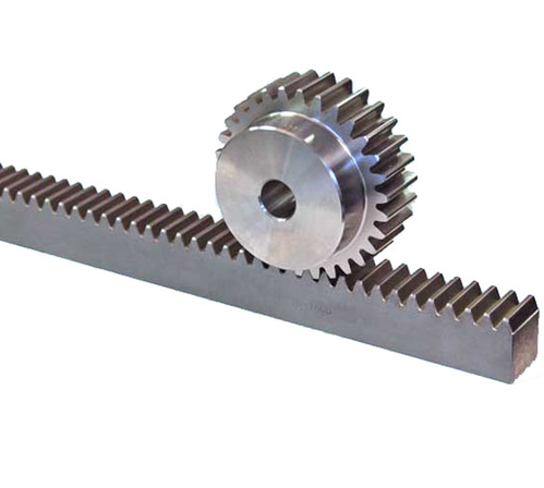
Rack and pinion type gears are used when we want to convert rotational motion to linear motion and vice versa. One of them is a small gear, called pinion, while the other one is a flat bar having teeth on its surface. Both has to mesh with each other. Its working can be easily understood by looking at its diagram.
