TABLE OF CONTENTS
ABSTRACT
Using the torsion testing machine, we will find out modulus of rigidity and shearing property of mild steel specimen.
Main objective of torsion testing experiment is following,
- To find modulus of rigidity of test machine.
- To draw torque (T) Vs Angle of Twist (θ) Curve.
- To find Breaking Torque and shearing stress.
THEORY
To transmit power through a rotating shaft it is necessary to apply a turning force. The force is applied tangentially and in the plane of transverse cross section.
Within elastic limit modulus of Rigidity of material of circular cross-section is given by
G= TL/Jθ
T= Torque applied in N.m
L= Gauge length in m
J= polar moment of inertia of cross section of test specimen in m4.
θ= Angle of twist in radian.
Apparatus Required in Torsion test:-
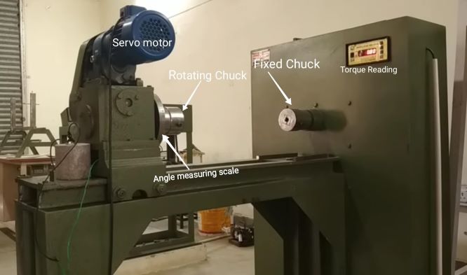
- Torsion testing machine with angle of Twist measuring setup,
- Standard specimen of Mild Steel,
- Vernier caliper or Outside Micrometer,
- Steel rule.

PROCEDURE
- With the help of driving dogs clamp the specimen between two chucks of the machine by adjusting the sliding spindle.
- The specimen has been held with the help of dog Holders in position and has been made tight within the holders by rotating the hand wheel till indicator is just on a position of showing deflection.
- Measure the diameter of test specimen at about 3 position with outside Micrometer and take the average value.
- Gauge length of test specimen has been measured with the help of steel rule.
- Set the maximum load pointer at zero value and .Angular scale or protractor on 0°.
- Now torque has been applied gradually by motor and corresponding reading of torque along with corresponding angle of twist has been recorded.
- Torque applied until fracture occurred.
OBSERVATION AND RESULT

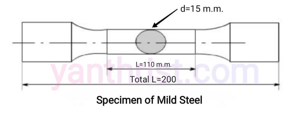
For the experiment we take a Mild Steel specimen as following,
Gauge length of the specimen, L =110 mm= 0.110 m
Diameter of the specimen, d =15 mm=0.015 m
Polar moment of inertia, J = π×d4/32 =π×(0.015)4/32=4.97×10-9 m4
From the following calculation we find out how to calculate modulus of rigidity in torsion test,
So Modulus of Rigidity for 2°, G= TL/Jθ= (158.92×0.110)/(4.97×10-9×0.035)= 100.7 × 10⁹ N/m2=100.7 GPA
Similarly Modulus of Rigidity for 4°, G=78.5 GPA.
So Within elastic limit( i.e 2°-4°) Average Modulus of Rigidity= (100.7+78.5)/2= 89.6 GPA.
| Sl No. | Angle of Twist in Degree | Angle of Twist in radian | Torque in kg.m | Torque in N.m | Modulus of Rigidity (G) |
| 1. | 2° | 2°×π/180 =0.035 | 16.2 | 16.2×9.81 =158.92 | 100.7 |
| 2. | 4° | 0.070 | 25.3 | 248.19 | 78.5 |
| 3. | 90° | 1.571 | 33 | 323.73 | 4.56 |
| 4. | 180° | 3.142 | 38 | 372.78 | 2.62 |
| 5. | 270° | 4.712 | 41.1 | 403.191 | 1.89 |
| 6. | 360° | 6.283 | 42.80 | 419.868 | 1.47 |
| 7. | 410° | 7.156 | 43.30 | 424.773 | 0.187 |

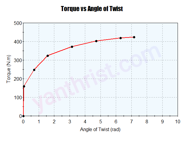
From the data of above table Torque Vs Angle of Twist Graph is plotted.
The breaking Torque=424.773 N.m
Maximum shear stress, fs=TR/J= (424.773×0.0075)/4.97×10-9= 641×106 N/m2=641 Mpa
FAQ
1. State the precautions to be taken in Torsion test experiment.
Grip the specimen within the holders properly with help of allen key so it is not damaged or bent.
Specimen Rod must be straight and enough length for experiment.
Torque must applied gradually.
2. Define torque. Give the expression for torque.
Torque is twisting or turning force that causes an object to rotate along its axis. It also called moment of a force. As it’s a product of two vector, it’s also a vector quantity.
S.I unit of Torque= N.m.
Torque τ = F x r x Sinθ
Where F= Linear force, r= distance between the axis of rotation and the point at which linear force is applied,
θ= Angle between the r and F.
3. State difference between torque and couple.
Torque is produced due to a single force but couple is different than torque is generated when two equal but opposite direction forces acts and are separated by a perpendicular distance such that their lines of action don’t cross each other, resulting in a turning effect.
4. What is difference between torsional rigidity and torsion stiffness?
Torsional stiffness is a characteristic property of a metal which indicates how much rigid is the material. The tensional stiffness K can be defined as the torque required per radian of twist,
K = T / θ = GJ / L. SI unit of torsional Stiffness N.m/rad
Torsional Rigidity is the product of modulus of rigidity and polar moment of inertia i.e G×J. SI unit of torsional Rigidity N.m2
5. Define modulus of rigidity.
Modulus of rigidity is defined as the ratio of shear stress to the shear strain.
S.I unit of Modulus of Rigidity is Pascal /Giga pascal (GPa). Dimension of Modulus of Rigidity= [ML-1T-2].
6. What is Torsion equation.
Torsion equation is given by below,
T/J =fs/R= Gθ/L
T= maximum twisting torque (N.m),
J = polar moment of inertia (m4 ) = π×d4 /32,
fs = shear stress (N/mm2)
G = modulus of rigidity (N/mm2)
θ = angle of twist in radians,
L= length of shaft under torsion (m)
7. State assumptions made for getting torsion equation.
- The shaft material should be uniform throughout.
- The cross section(circular) of shaft not to be changed after loading.
- Twist along the length of the shaft should be uniform.
- Plane sections of shaft perpendicular to axis before loading have to be remain plane after the torque applied.
- The distance between any two normal-sections remains the same even after torque applied.
- Maximum shear stress in the shaft should not exceed its elastic limit.
8. Give the values of “G” for different materials.
modulus of rigidity is a material property that is constant at a particular temperature for given material. Here are some value of modulus of rigidity of different materials given below,
- Pure Aluminum= 26 Gpa,
- Brass= 36-41 Gpa,
- Copper=30-50 GPa,
- Bronze= 36-44 Gpa,
- Steel=80-100 GPa,
- Cast Iron= 32-69 Gpa,
- Zinc= 43,
- Cold rolled mild steel 79-80.

