Study performance characteristics test of a centrifugal pump – Experiment
Table of Contents
Objective of the Experiment:
(i) To study the components of a centrifugal pump.
(ii) To obtain the performance characteristics of the centrifugal pump.
(iii) To find the efficiency of the centrifugal pump.
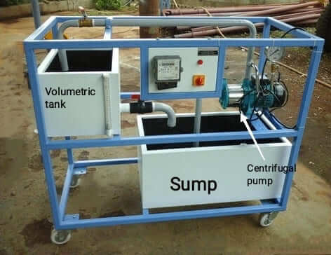
Apparatus used for Centrifugal Pump Test :
1. Centrifugal pump
2. Volumetric tank
3. Stop watch
4. Pressure gauge
5. Thermometer
6. Energy meter
7. Gate valve.
Specifications:
a. Centrifugal pump – 25×25 mm² base mounted, Max. head 20 m, Max. discharge 84 lit/min at 2700 rpm.
b. Motor – 1 HP 3 phase Induction motor, approx. efficiency of the motor is m 65%.
c. sump tank- 900 x 300 x 400 mm3
Theory of Centrifugal Pump:
Centrifugal pumps are used to transport fluids by the conversion of rotational kinetic energy to the hydrodynamic energy of the fluid flow. The rotational energy typically comes from an engine or electric A.C motor. The fluid enters the pump impeller along or near to the rotating axis and is accelerated by the impeller, flowing radially outward into a diffuser or volute chamber (casing), from which it exits. Input at motor is measured by energy meter. A measuring tank is provided to measure the discharge. Suction vacuum and discharge pressure is measured by gauges fitted with it. A gate valve on discharge pipe varies the head. Finally, performance of pump can be estimated at various speed and heads.
In principle, Pump is just the opposite of a turbine.
Centrifugal Pump Experiment Procedure:
1. Fill the sump tank with sufficient water.
2. Open the priming cock (fitted on the delivery pipe ) and fill up water up to the funnel. Close the cock properly.
3. Shut off the discharge valve.
4. Start the pump. As discharge valve is closed, no discharge will be observed, but discharge pressure will be indicated. This is called “Shut off head” of the pump.
5. Now slowly open the discharge valve, so that small discharge is observed.
6. Take readings of discharge head, suction vacuum, time required for 10 cm rise in the measuring tank 10 impulses of energy meter.
7. Take readings for different valve openings.
Determination of input power:
For n number of blinks of energy meter required tₑ second
Electrical input power to the motor,Pinput motor= 3600n/3200tₑ KW. [Energy meter constant= 1600 rev/kWh]
Electrical input power to the pump,Pinput pump= 3600n/3200tₑ KW.
Determination of output power:
The output power Pₒ= γQH/1000 KW
Where, γ= ρg= specific weight of water, Q= Discharge in m³/sec, H= Head developed in meter.
Efficiency of the pump ηpump =(Pₒ/Pinput pump)×100 %
Observations:
Temperature of water= 20°C Cross sectional area of the volumetric tank (A)= 30×30 cm²


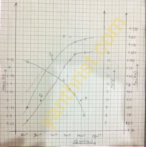
Required Graph to be plotted:
(i) ‘H’ vs ‘Q’,(ii) ‘ηpump’ vs ‘Q’,(iii) ‘Pinput pump’ vs ‘Q’ in normal graph paper.Note All 3 graph plotted on same graph paper for better understanding. To draw a continuous proper graph some point of reading is to be ignored.
FAQs Related to Centrifugal Pump:
1. Draw the schematic diagram of the setup.
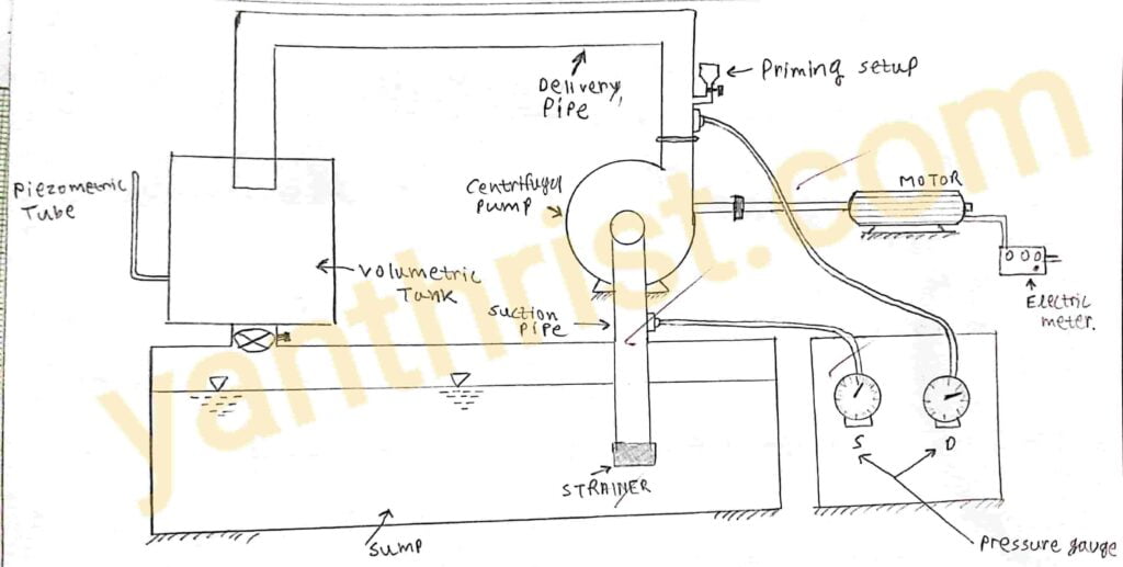
Centrifugal pump experimental setup
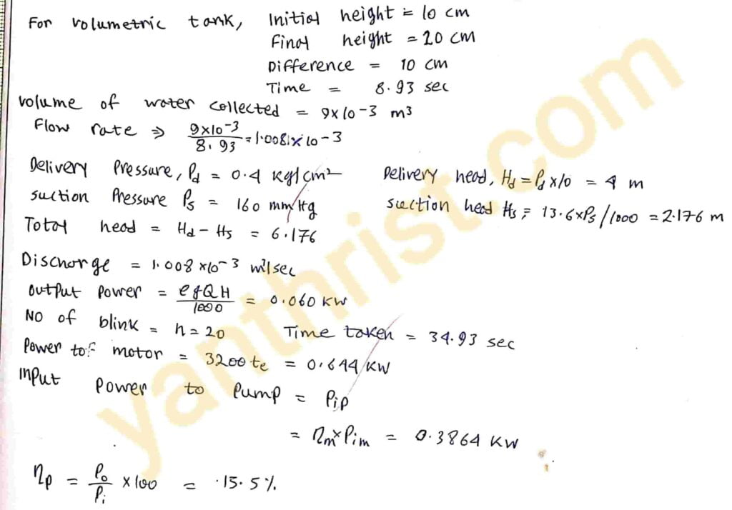
2. Provide sample calculation.
3. Describe principle of operation of the centrifugal pump.
In a centrifugal pump which is radial flow pump, the angular momentum of the fluid is increased by rotating the impeller. Then increased Momentum is utilised as pressure head to lift the fluid from low level reservoir to a high level reservoir. The function of impeller eye is to smoothly smoothly turn the flow from axial to radial direction.In volute casing the fluid from impeller is collected. The absolute flow velocity is reduced to cause a further increase a further increase of head and fluid is discharged into delivery pipe.
4. Identify each component of a centrifugal pump and briefly state their function.
IMPELLER:- The rotating part of pump is called impeller. It consists a series of backward curved vanes. it converts mechanical energy to pressure energy.
VOLUTE CASING:- The casing of the centrifugal pump is of Volute shape having gradually increasing cross-sectional flow area. It helps in further increase of pressure energy by reducing the kinetic energy.
SUCTION AND DELIVERY PIPE:- as the name implies it acts as a medium through which water flows in suction and delivering line respectively.