TABLE OF CONTENTS
ABSTRACT
Micrometer is used to measure inside or outside diameter of a product like shaft diameter, Thickness of plates. Here we mainly discussed about outside Micrometer only that used to measure external diameter or shaft thickness of parts of an accuracy upto 0.01 mm.
PARTS OF MICROMETER
1. Frame
The outside structure of Micrometer i.e frame made of drop forged steel, cast steel, steel, malleable cast iron or light alloy. Each other parts attached to this.
2. Hardened Anvil
The anvil is attached on frame, projected out upto a distance of 3 mm to give support to the measurable job piece. It’s a measuring flat face made of alloy steel.
3. Screwed spindle
This is actual measuring spindle which has threads of 0.5mm pitch. It grips the job piece against anvil and can move forward and backward by its threaded mechanism.
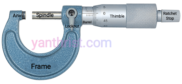
4. Graduated sleeve or Barrel:-
it is fixed on frame. Dimension is marked on this along with datum line.
5. Thimble
This is a tubular cover fasten with the spindle and moves with spindle.it has one side beveled which is divided into 50 equal parts, every 5th part is numbered i.e 0,5,10…45.
6. Ratchet or Friction Stop
This is a small extension part to the thimble. The ratchet slips when the pressure on screw exceeds a certain limit. It helps to give uniform pressure between measuring faces and prevent any damage.
7. Spindle clamp or Clamp ring
This is used to fix or lock the spindle at a desired position.
WORKING PRINCIPLE OF MICROMETER
it works on the principal of screw and nut. The longitudinal movement of spindle is same as pitch during one revolution of thimble. The distance moved can accurately measure by by thimble marking.
In Micrometer screw has a pitch of 0.5 mm i.e. one full revolution of thimble, spindle advances 0.5 mm. Barrel is marked 0-25mm and each mm divided in half mm. Circumference of bevel edge of thimble is divided into 50 division that means one division movement of thimble is 0.01 mm i.e. called Least count.
Hence least count of Micrometer= [Pitch of screw/Number of division on thimble]
How to read an Outside Micrometer
The job is measured between the end face of spindle. To take reading we have to observe 3 things
- Major division:- The number of main division in mm above datum or reference line i.e. number of Full mm.
- Minor division:- The number of subdivision below reference line i.e. number of Half mm.
- Thimble division:- The number of division on beveled edge or circumference against datum line.
Let’s see the picture below where
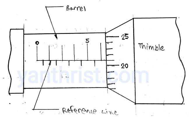
6 Major division above reference= 6×1 mm=6 mm
0 Minor division below reference= 0 mm (So NO half mm reading added here)
21 Thimble division on circumference= 21×0.01= 0.21 mm
Total reading= 6.21 mm
FAQ
1. What is Zero error in Micrometer?
First move the spindle until it touches with anvil face. Now check if Zero mark of thimble aligned with reference line of barrel, if not then Micrometer has a zero error.
If it exceeds 0 then it’s called Minus Zero error which subtracted from final reading.
If it less than 0 then it’s called Plus Zero error which Added to final reading.
2. How to Calibrate Outside Micrometer?
- Adjust nut fixed inside thimble of Micrometer.
- Adjust barrel of Micrometer with the C spanner.
- Sometimes Anvil is adjusted by screwing or unscrewing it manually to make it error free.
3. How to use a Outside Micrometer?
- Clean spindle and anvil face with soft cloth.
- check for Zero error if any calibrate it.
- Make a gap bigger than job between both faces.
- Hold the job against anvil and rotate ratchet Stop slowly until it slips or produce ratchet click sound.
- Ensure measuring parts are right angle to the micrometer.
4. What is the common errors in Micrometer reading?
- Too much pressure applied on thimble.
- Flat faces or job is not cleaned properly.
- screw is loosely fitted, worn out.
- Zero error from beginning.
- Micrometer frame is bent.
5. What is the necessary care and maintenance of Micrometer should be taken?
- Clean anvil and spindle faces properly.
- Use it gently don’t apply pressure excess. Always stop rotation after click sound.
- Oil screw thread properly.
- Keep Micrometer in case when not in use.
- Don’t keep the faces in contact with job while not using.