Experiment Name: STUDY PERFORMANCE CHARACTERISTICS TEST OF FRANCIS TURBINE
Table of Contents
Objective:–
(i) To study different components of a Francis Turbine.
(ii) Find the operating characteristics of the Francis Turbine.
(iii) To obtain the efficiency of the Francis Turbine.
Apparatus Used:
1. Francis Turbine,
2. Pressure Gauges,
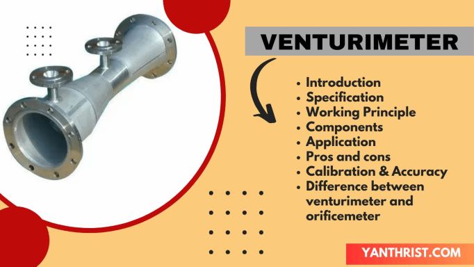
3. Venturimeter,
4. Brake drum.
Specification:
Rated Supply head (H)=25 m
Rated Discharge (Q)= 2000 lpm
Normal Speed (N)= 1250 rpm
Runner diameter = 160 mm
No. of guide vane=10
P. C. D. of guide vane =230 mm
Brake Drum diameter = 200 mm
Rope diameter =16 mm
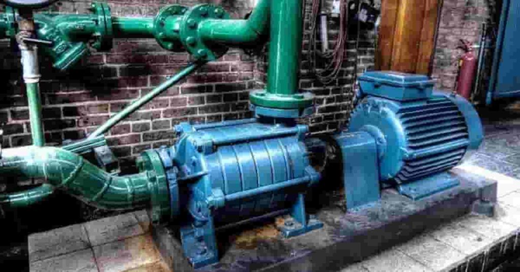
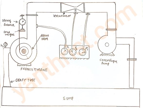
Experimental setup:
The Francis turbine is placed on the sump tank level. The supply pump-set used for supplying the water to the turbine. To measure the flow rate to the turbine a venturimeter set is used. The gate valve is placed at the inlet side of the turbine to regulate supply head. The water flowing through the inlet guide vane (IGV) comes to the turbine runner. The IGV opening can be regulated by a hand wheel.
Experimental procedure:
1. Check lubrication of the ball bearings, and make sure the pipelines are free from foreign material.
2. Close the gate valve and the spear at the turbine inlet.
3. Make the hanger load free and Start the pump.
4. Slowly open the gate valve and check the supply rated head by the reading of the pressure gauge.
5. Slowly open the IGV by hand wheel.
6. Check the steady rotation of the turbine.
7. Take the Pressure gauge reading.
8. Hang the load on the hanger.
9. Due to the applied load the speed of the turbine will be decreased,
10. Adjust the rated speed by changing the IGV opening.
Theory:
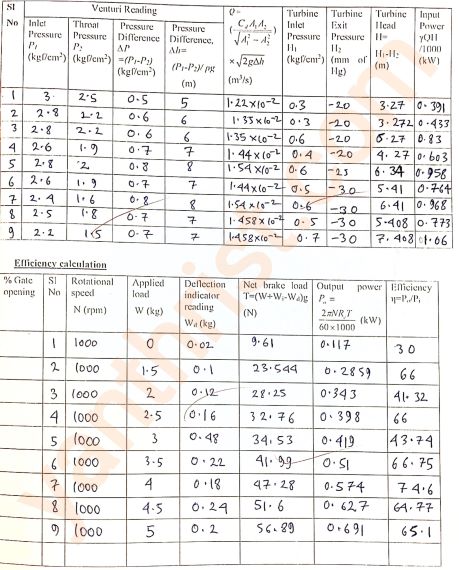
input power:-
The input power Pinput = γQH/1000 KW
Where,γ= ρg= specific weight of water,
Q= Discharge in m³/sec,
H= Supply head in meter.

∆h= Difference in pressure gauge reading of venturimeter in terms of head.
A1= Inlet area of the venturimeter.
A2= Throat area of the venturimeter.
Cd= Discharge coefficient of the venturimeter = 0.962
Output power:-The output power Poutput =2πNReTg/(60×1000) KW
Where,N= Turbine shaft rotational speed r.p.m.
Re= Effective radius of the brake drum.
T= Net brake load.
Data to be collected before starting the experiment:-
Temperature of the water= 20°C,
Density of the water (ρg)= 1000 kg/m³,
Venturimeter inlet diameter (D1) = 0.05 m,
Venturimeter throat diameter (D2) =30 m,
Brake Drum diameter (D)= 0.2 m
Rope diameter (t)= 0.016 m
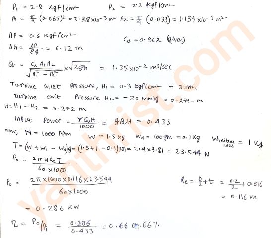
Effective radius Re= (D/2+t)= (0.2/2) + 0.016= 0.116 m
Weight of the rope and hanger (Wi)= 1 kg.
(Note:- Sample Francis turbine calculation are shown below for input power and efficiency calculation.)
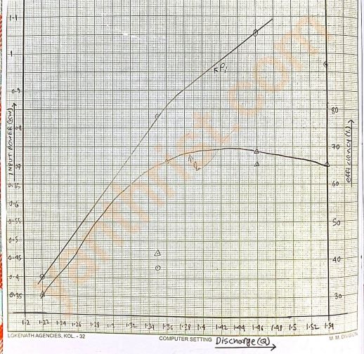
Required Graph to be plotted:
A. Input Power vs Discharge.B. Efficiency vs Discharge.
Note:- Both graphs are drawn on the same graph paper for better understanding. To draw a continuous proper graph some point of reading is to be ignored.
FAQ:
1. Draw the schematic diagram of the setup.
2. Provide sample calculation.
3. What is Francis turbine explain?
The Francis turbine is a inward-flow reaction turbine that combines radial and axial flow both, which means that the working fluid changes pressure as it travels through the turbine by consuming its energy. The turbine is located between the high-pressure water source and the low-pressure water exit, generally at the foundation of a dam.
4. What are the main components of Francis turbine?
Spiral Casing
The casing of Francis turbine is of spiral shape with gradually decreasing flow area where Pressure energy is converted into Kinetic or momentum energy.
Guide Vanes–
Between casing and runner inlet there is a series of vanes which guides the fluid flow into the runner so that Vw becomes zero. it also accomplished in increasing kinetic energy.
Runner Blades
It is a main component of turbine.At first the water hits the runner blade and its energy is transferred and transform into mechanical energy.
Draft Tube
Draft tube is a tube of gradually increasing flow area attached at the end of outlet of turbine to recover the kinetic energy from outlet of water in turbine. it creates a negative head which helps to increase overall head and reduce loss.
5. Why is Francis turbine preferred?
Among other hydraulic turbine that is commonly used in hydroelectric power plants, Francis turbines are preferred in many applications because it has several advantages:
A. High efficiency: Francis turbine has comparatively more efficient. It can convert a more percentage of the energy of water into mechanical energy means generate more electricity in hydroelectric power plants.
B. Wide range of operation: It can be operated over a wide range of flow rates and head heights, which helps them use in different hydroelectric power plants.
C. Simple construction: Francis Turbine has simple construction, which makes them easy to manufacture and maintain. it also reduce the overall cost of operating of power plant.
D. Reliable operation: Francis turbines are known for their reliable operation, which makes them a popular choice in hydroelectric power plants.